Flotation is one of the most widely used methods in mineral processing. But when something goes wrong, it can cost you tons of lost recovery and wasted reagents every single day. Drawing upon our experience, we will conduct an in-depth analysis of five practical challenges faced by operators, offering clear and practical solutions for each specific issue.
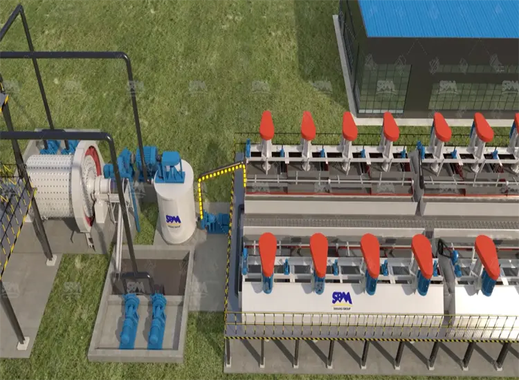
Flotation separates valuable minerals from waste rock using air bubbles. Hydrophobic (water-repelling) mineral particles attach to bubbles and rise to the froth layer. Hydrophilic (water-attracting) gangue particles sink and leave as tailings.
The process sounds simple. But it depends on a tight balance of chemistry, particle size, air flow, and pulp density. If any one of those shifts, recovery drops fast. Most operations see 3–8% recovery loss from fixable process problems — which means fixing them has a direct impact on your bottom line.
Froth that collapses before it reaches the launder carries your minerals back into the pulp. You lose recovery without even knowing why.
Common causes include:
How to fix it: First, measure your froth depth. Target 10–25 cm for sulphide ores (varies by ore type). Then adjust frother dosage in small steps — typically 20–50 g/t MIBC or equivalent. If your feed is coarse, check that your grinding circuit is producing 65–75% passing 75 µm for most sulphide applications. If you operate in cold regions, consider insulating pulp lines or pre-heating process water above 15°C.
A stable froth moves slowly toward the launder and has a glassy, mineral-rich surface. If it looks watery and thin, your frother is under-dosed. If it’s too stiff and dry, reduce frother or increase wash water.
Low recovery means valuable minerals are leaving in the tailings stream. This is the most expensive problem in flotation — and it often has more than one cause happening at the same time.
Main reasons for poor recovery:
How to fix it: Start with a liberation audit. Run a mineralogical analysis (MLA or QEMSCAN if available, or manual sizing) to confirm your grind P80. For copper sulphides, a common target is P80 = 150–210 µm. For finer-grained ores, grind to P80 = 75–106 µm.
Next, check collector dosage. Xanthate dosage typically runs 30–150 g/t depending on ore grade and mineralogy. Increase in 10 g/t steps and monitor recovery response over 2–4 hours. Also check your cell bank retention time — most rougher circuits need 10–18 minutes of total residence time to achieve design recovery.
Grade swings in your concentrate cause contract penalties and smelter rejections. Inconsistency usually points to feed variability or reagent control problems.
Key causes of grade variation:
How to fix it: Install a flow-proportional reagent dosing system. This adjusts reagent addition automatically as feed tonnage changes. Many older plants still use fixed-rate dosing — switching to flow-proportional dosing alone can reduce grade variance by 15–30% in typical operations.
Monitor and control pH closely. For many sulphide systems, pH 8.5–9.5 gives best selectivity between target minerals and iron sulphides. Use lime addition upstream of flotation, and check pH at each cell bank. A pH swing of just 0.5 units can shift recovery by 2–4%.
Reagent costs typically make up 20–35% of total flotation operating costs. If your consumption is above benchmark, you may be compensating for a process problem rather than solving it.
Typical reagent consumption benchmarks:
| Reagent Type | Typical Dosage Range (g/t) | Function |
|---|---|---|
| Xanthate collector | 30–150 | Makes mineral surface hydrophobic |
| MIBC frother | 20–60 | Controls bubble size and froth stability |
| Lime (pH modifier) | 500–3000 | Controls pH, depresses pyrite |
| Copper sulphate (activator) | 50–300 | Activates sphalerite or oxidised surfaces |
| Zinc sulphate (depressant) | 200–1000 | Depresses sphalerite in Cu circuits |
If your numbers are above these ranges, first check for process leaks. A broken reagent line or leaking pump can waste large volumes without triggering an obvious alarm. Then check if your ore has changed — higher oxidation or clay content can increase collector demand significantly.
Another common issue is poor mixing. If collectors are added too close to the flotation cell, they don’t have time to adsorb onto mineral surfaces. Move collector addition points to the conditioning tank, allow 3–5 minutes of contact time before the feed enters the first cell.
Even with perfect chemistry, a worn or misadjusted cell will underperform. Mechanical issues are often overlooked because they develop slowly over time.
Common mechanical problems and their symptoms:
How to fix it: Set up a quarterly inspection schedule for impellers and stators. Most manufacturers recommend replacement when impeller tip clearance exceeds 3–5 mm beyond original spec. Track power draw per cell — a drop of more than 5–8% from baseline usually means internal wear.
Check air flow with a simple aeration test. Fill the cell with water, run the impeller, and observe bubble distribution. Bubbles should be uniform across the full cell area. Dead zones in corners or along one wall usually mean a blocked sparger or misaligned draft tube.
| Component | Check Interval | Replacement Trigger |
|---|---|---|
| Impeller | Quarterly | Tip clearance >4 mm or visual erosion |
| Stator | Quarterly | Blade wear >20% of original thickness |
| Dart valve / gate | Monthly | Level control deviation >±3 cm |
| Shaft seal | Monthly | Visible air leakage at shaft |
| Froth paddles | Bi-annual | Bent blades or off-speed drive |
Choosing the right cell type and size affects capital cost, energy use, and how easy the plant is to operate. There is no single best option — it depends on your ore, throughput, and available space.
| Cell Type | Typical Volume Range | Best For | Key Advantage | Main Limitation |
|---|---|---|---|---|
| Mechanical flotation cell | 0.3 m³ – 300 m³ | Rougher, scavenger, cleaner | Flexible, well-understood | Higher energy per tonne |
| Column flotation cell | 0.5 m dia. – 4 m dia. | Cleaner circuits, high-grade concentrate | High selectivity, wash water | Sensitive to feed fluctuations |
| Pneumatic flotation cell | Small–medium scale | Fast-floating ores, coarse particles | No moving parts, low maintenance | Less control on air dispersion |
| Jameson cell | Small–large scale | High-throughput sulphide circuits | Compact, high intensity contact | Requires stable feed pressure |
For most new projects, mechanical cells in the rougher and scavenger duty, combined with column cells in cleaners, gives the best combination of recovery and grade control. This configuration is well-documented in literature including work published in Minerals Engineering journal and the SME Mineral Processing Handbook.
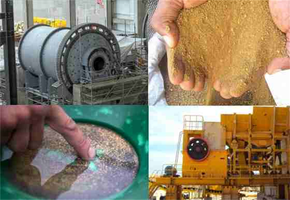
A copper sulphide operation in a high-altitude, cold-climate region was running 78% Cu recovery — well below the feasibility study target of 86%. Feed grade was 0.62% Cu. The ore contained chalcopyrite with moderate pyrite content and some secondary oxidation near surface.
The processing team identified three linked problems: grind P80 was running at 210 µm (target was 150 µm), xanthate dosage was fixed at 45 g/t regardless of feed rate, and cell impellers in the rougher bank had not been replaced in 26 months.
Changes made over a 6-week period:
Results after 60 days of stable operation: Cu recovery improved from 78% to 87.3%. Concentrate grade held at 28–30% Cu consistently. Reagent cost per tonne of ore actually dropped 12% because over-dosing of frother to compensate for mechanical issues was eliminated.
The site metallurgist noted that after the impeller replacement, the cells were “much easier to control — the froth behavior became predictable for the first time in years.” The maintenance team also reported that monthly inspection time per cell dropped from 4 hours to under 2 hours, because worn components had been causing secondary damage to cell liners and drive shafts.
Flotation optimization projects generally have short payback periods compared to other capital investments. Recovery improvements of 3–5% on a plant processing 2,000 t/d at 0.5% Cu grade represent meaningful additional metal output every month.
The main cost categories to consider are reagent system upgrades, mechanical component replacement, control system improvements, and any grinding circuit adjustments needed to achieve target liberation. In most cases, reagent and mechanical fixes carry the lowest capital requirement and the fastest payback.
Energy is also worth tracking. A flotation circuit running oversized cells at low fill levels, or with worn impellers drawing excess power, can use 15–25% more energy than a well-maintained circuit of equivalent capacity. Tracking kWh per tonne of concentrate produced gives a useful baseline for measuring improvement.
When you purchase flotation equipment, the commissioning phase is where most early problems appear. Proper installation alignment, correct impeller-to-stator clearance setting, and verified air flow calibration before start-up all reduce the risk of early failures.
A responsible equipment supplier should provide:
We provide full installation supervision and commissioning support for every flotation circuit we supply. Our technical team stays on-site until your plant reaches stable design performance — not just mechanical completion. We also offer customized maintenance programs based on your specific ore type, climate conditions, and shift structure.
The fastest way is a float-sink or sink-float test on your current plant feed. Take a sample of your flotation feed, screen it at your target grind size, and run laboratory flotation tests on each size fraction separately. If the coarse fractions (+150 µm) show much lower recovery than the fine fractions (–75 µm), the problem is liberation — you need finer grinding. If all size fractions show poor recovery, the problem is more likely chemistry: collector type, dosage, or pH. This test takes 1–2 days in a basic metallurgical lab and gives you a clear direction before you spend money on process changes.
Overly stable froth usually means too much frother, or a frother type that is too strong for your ore and cell geometry. First, reduce frother dosage in steps of 5–10 g/t and observe froth mobility after each change. If froth remains stiff, try switching frother type — for example, moving from a polyglycol frother to MIBC, which gives less stable froth. Adding wash water to the froth layer at 0.5–1.0 m³/h per metre of cell width also helps break up stiff froth in cleaner circuits. Avoid increasing air flow to try to push stiff froth out — this creates larger, less selective bubbles and usually drops your concentrate grade.
There are several practical steps. First, audit which reagents are truly critical versus which ones can be substituted in an emergency — for most sulphide circuits, you need a collector and a frother at minimum; pH modifiers can sometimes be reduced temporarily. Second, build a 60–90 day strategic stock of your highest-risk reagents, particularly specialty collectors that have long lead times. Third, work with your equipment and reagent suppliers to qualify at least one alternative product for each critical reagent — so if your primary supply is disrupted, you have a tested backup. We can support this audit and help you develop a contingency reagent plan as part of our technical service offering.
Flotation problems are almost always fixable — and most fixes do not require major capital. What they require is a clear diagnosis, the right equipment, and support from people who understand both the process and the machinery.
We design and manufacture complete flotation circuits for sulphide, oxide, and industrial mineral applications. Every solution is engineered to your specific ore characteristics, throughput, and site conditions. We also supply individual cells, reagent systems, and wear parts for retrofit into existing plants.
If your recovery is below target, your reagent costs are climbing, or you are seeing inconsistent concentrate grade — contact our technical team today. Describe your current setup and your main pain point, and we will come back to you with a concrete assessment and suggested next steps. No generic proposals — just a focused response to your actual problem.
Whatsapp:+8617329420102
Email: [email protected]
Address: No. 1688, Gaoke East Road, Pudong new district, Shanghai, China.
Online Service : Get Price

We value your feedback! Please complete the form below so that we can tailor our services to your specific needs.
