Abstract: This practical guide explains, step-by-step, how to determine, set and control the grinding media charge (charge volume) in ball mills and rod mills. Drawing on long field experience and verified product data — including model capacities, ball/rod loading and motor power — the article gives operational rules, calculation checks, monitoring tips, and clear selection guidance for engineers and plant operators. Moreover, it cites tested model parameters to anchor recommendations.
Charge volume is the physical volume inside the mill cylinder occupied by grinding media and retained material, expressed as a percentage of mill internal volume. In practice, we target a media filling rate and a pulp-surface level to achieve stable grinding,; in short, charge volume = media + slurry volume.
Charge volume controls impact energy transfer, grinding rate and product size distribution. Too high charge reduces impact and increases sliding; too low charge shortens retention time and lowers throughput. Therefore, correct charge ensures predictable capacity, lower specific energy consumption, and lower maintenance.—
First, measure internal mill volume; second, determine desired media filling rate (typical ball mills 40–50% by volume); third, set pulp level relative to grate or overflow. Also check critical speed and mill rotation speed; speed is usually 65–80% of critical speed for ball mills. These parameters together determine grinding kinetics and classification load.
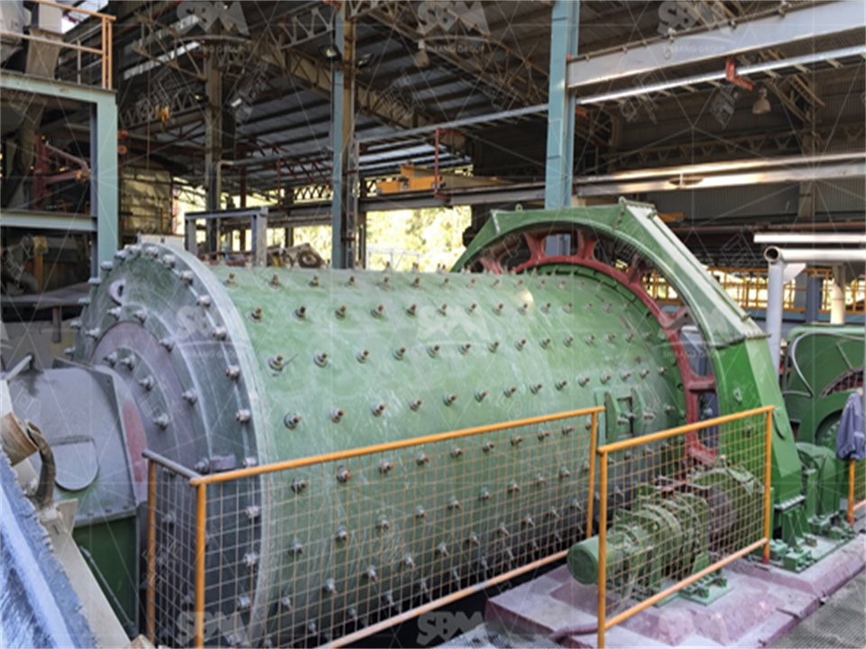
Record: model designation, internal effective volume, ball/rod loading (t), feed size, target product size, motor rating, and observed throughput. For example, common ball mill models show clear rated ball loads and motor powers; a Ф1500×5700 model lists ~12 t ball load and 130 kW motor, with capacity 3.5–6 t/h. Similarly, rod mill models (e.g., MBS(Y)-1530) list diameter, length, effective volume and max rod loading. Use those numbers as baseline for calculations.
1) Compute internal cylinder volume V = π·(D²/4)·L (m³). 2) Decide media filling fraction f (e.g., 0.40–0.50 for ball mills; lower for rod mills). 3) Initial media mass = f·V·ρ_media (use ρ ≈ 7.8 t/m³ for steel). 4) Verify motor power match: motor_kW ≥ required_kW for the projected throughput. 5) Set pulp fraction (slurry) to obtain target circulation; adjust feed rate accordingly. These steps give a practical first-charge; then fine-tune online.
• Ball mills: start at 40% media filling, then adjust ±3–5% while watching mill sound, draw, and throughput. • Rod mills: use lower media fill and longer rods; aim to avoid over-grinding. • Grid vs overflow: grid mills usually produce coarser product at higher throughput; overflow mills fine product but lower throughput. Use this when choosing discharge type.
When first charging, use a graded mix: large balls 30–40%, medium 30–40%, small 30% (example distribution). For Ф1500×3000 class ball mills, documented ball-loading guidance indicates mixed sizes to optimize breakage. Monitor wear and replace proportionally.
Track these plant signals: throughput (t/h), mill power draw (kW), mill sound/torque, product particle size (e.g., % passing 74 µm), and circulating load. If power draw increases without throughput gain, check overcharging or trapped tramp material. Conversely, falling power and coarser product imply under-fill or worn media. Use simple daily logs, and calibrate weekly.
Replace steel media in staged batches every maintenance window; avoid full-swap because production stops. Inspect liners and bolts at scheduled intervals; typical heavy-duty mills show long intervals but require rubber/steel liner checks every months. Keep lubrication consistent for bearings; vibration or heating signals mean immediate inspection.
Consider a plant with feed 25 mm top size, desired product -0.074 mm, and target 6 t/h. A Ф1500×5700 ball mill (ball load ~12 t, motor 130 kW) is a plausible match per machine data; start with 42% media filling, set rotation speed to ~75% critical, then tune feed to reach 6 t/h while monitoring kW draw and product fineness. For coarser circuits, a grid type may give +10–15% throughput at same size.
When selecting mill size and charge strategy, confirm: rated ball/rod load, feeding/discharge size limits, motor power, cylinder length/diameter, and expected capacity. Also validate factory test reports, and request model-specific operating curves. Compare several models on power per tonne metrics before ordering.
• Problem: Low throughput + low power → increase media fill slightly, or reduce feed rate. • Problem: High power + low throughput → check for overfill, foreign object, or liner damage. • Problem: Product too fine → reduce grinding time or decrease media density. • Problem: Excess fines and energy waste → consider coarser media or reduce rotation speed. These rules help make timely, low-risk changes on site.
| Model | Ball/Rod load (t) | Feeding size (mm) |
|---|---|---|
| Φ900×3000 (ball) | 2.7 | <20 |
| Φ1500×5700 (ball) | 12 | <25 |
| MBS(Y)-1530 (rod) | 8 (max) | — |
1. Use documented model data as baseline; then calibrate charge empirically. 2. Start ball mills at ~40–45% media fill; rod mills lower. 3. Log power, throughput, and fineness daily. 4. Replace media by staged batches, not full swaps. 5. Prefer grid discharge where throughput matters; overflow when product fineness is critical. These steps minimize downtime, and reduce energy cost.
Handling charge volume is both art and science. Use geometric calculation, factory model parameters, and then iterate with measured signals. With that method, you will secure consistent capacity, controlled product size, and reliable, low-cost operation.
Whatsapp:+8617329420102
Email: [email protected]
Address: No. 1688, Gaoke East Road, Pudong new district, Shanghai, China.
Online Service : Get Price
We value your feedback! Please complete the form below so that we can tailor our services to your specific needs.
