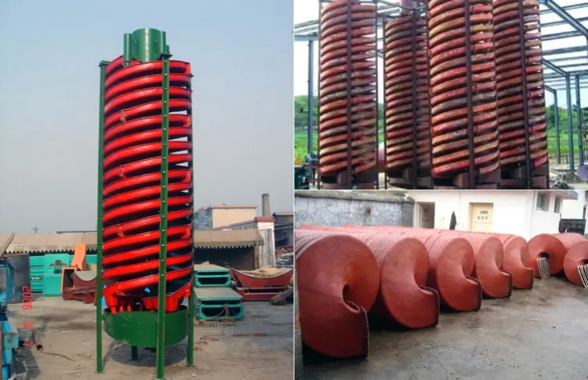
A spiral chute separates minerals by density using water flow and centrifugal force — no chemicals, no moving parts. It handles fine particles from 0.03 mm to 2 mm, which most gravity machines struggle with. Plants that process beach sand, iron ore, or chrome ore often rely on spiral chutes as their core separation unit.
A spiral chute is a helical trough mounted on a vertical column. Feed slurry enters at the top. As it flows downward, two forces act on the particles: gravity pulls them inward, and centrifugal force pushes them outward. Heavy minerals settle near the inner edge. Light minerals and gangue move to the outer edge. Splitters at the bottom separate these bands into product streams.
The pitch angle of the trough — usually between 8° and 12° — controls the flow speed. A steeper pitch moves slurry faster, which suits coarser feed. A shallower pitch slows the flow and improves separation of fine, close-density particles. The trough surface is typically made from polyurethane or fiberglass-reinforced resin, both of which resist abrasion well.
Before selecting a spiral chute, check these numbers carefully. They determine whether the unit fits your ore and your target grade.
These ranges come from standard gravity separation practice used in mineral processing plants worldwide. If your feed falls outside these bounds, you likely need a different separation method — such as a jig or shaking table.
Choosing the right gravity unit depends on your ore type, particle size, and throughput needs. This table shows where the spiral chute stands compared to common alternatives.
| Equipment | Feed Size Range | Throughput (per unit) | Best Use Case | Power Needed |
|---|---|---|---|---|
| Spiral Chute | 0.03 – 2 mm | 0.5 – 4 t/h | Fine beach sand, iron ore, chrome ore | None (gravity-driven) |
| Shaking Table | 0.02 – 2 mm | 0.1 – 1.5 t/h | High-grade concentrate cleaning | 0.5 – 1.5 kW |
| Jig Machine | 0.5 – 30 mm | 5 – 50 t/h | Coarse coal, alluvial gold | 2 – 15 kW |
| Centrifugal Concentrator | 0.01 – 1 mm | 0.5 – 100 t/h | Free gold, very fine heavy minerals | 3 – 30 kW |
| Magnetic Separator | 0.05 – 3 mm | 2 – 20 t/h | Magnetite, ilmenite, manganese | 1 – 10 kW |
The spiral chute uses zero electricity during separation. That alone makes it attractive for remote sites or operations with limited power supply. However, its recovery rate drops below 70% when feed density difference is less than 0.5 g/cm³, so close-density ores may need a different approach.
Many operators connect a spiral chute directly to a classifier overflow without checking solids concentration. If the slurry runs too thin — below 20% solids — particles won’t stratify properly. Heavy and light minerals mix together. Recovery falls sharply.
The fix is simple. Install a density meter on the feed line. Target 30% – 45% solids for most fine ore applications. If your classifier produces a dilute overflow, add a thickener or adjust your wash water rate upstream. Running trials at 25%, 35%, and 45% solids lets you find the sweet spot for your specific ore. Document the concentrate grade at each setting. That data becomes your operating baseline.
A spiral chute is sensitive to feed rate fluctuations. If feed jumps from 1 t/h to 3 t/h in the same hour, the water film depth changes. Particles don’t stay in their stratified layers. Heavy minerals get carried to the outer edge and report to tailings.
Consistent feed rate matters more than people expect. A simple solution is to use a surge tank before the spiral feed box. The tank buffers flow variations from upstream equipment. Pair it with a flow control valve and you keep the spiral running inside its optimal window. Most operations target ±10% variation around the design feed rate. Anything beyond that starts to hurt separation efficiency.
Clay is a real problem for spiral chutes. Clay particles are fine and light, but they coat heavy mineral surfaces and increase their apparent density. The coated particles behave like middlings and end up in the wrong stream. Recovery of valuable minerals drops, and concentrate grade suffers.
The standard approach is to scrub the ore before feeding the spiral. A log washer or attrition scrubber breaks up clay coatings. After scrubbing, a hydrocyclone removes the minus 20-micron clay slimes. What enters the spiral is a clean, de-slimed feed. Plants in laterite iron ore regions — parts of West Africa and Southeast Asia — routinely include a scrubbing stage for exactly this reason. Skipping it means running the spiral at half its potential efficiency.
Splitters at the bottom of a spiral chute divide the product bands into concentrate, middlings, and tailings. Most operators set them once during commissioning and forget about them. That works until ore characteristics change — which they always do over time.
A shift in feed grade or particle size distribution moves the mineral bands on the trough. If splitters stay fixed, you either pull diluted concentrate or lose recoverable mineral to tailings. The right practice is to check splitter positions every two weeks and after any significant ore blend change. It takes 20 minutes per spiral set. Grade and recovery data from your plant lab tells you immediately whether the adjustment is correct.
A beach sand operation in Vietnam processes ilmenite, zircon, and rutile from coastal dune sand. The ore is fine — 80% passing 0.3 mm — with high clay content from marine deposits. Annual rainfall exceeds 2,000 mm, and humidity stays above 80% year-round.
The plant installed a two-stage spiral circuit: rougher spirals followed by cleaner spirals. Each rougher column carries three starts of 1200 mm diameter spirals. Cleaner columns use 900 mm diameter units for a tighter cut.
The plant’s processing supervisor noted that installation took nine days for the full spiral circuit — simpler than the magnetic separator installation that followed. During a 14-month production run, there were zero mechanical failures on the spiral units themselves. The only unplanned stops came from feed pump issues upstream.
A chrome processing plant in Zimbabwe upgraded its fine ore recovery section. Previous equipment — a bank of shaking tables — couldn’t keep up with throughput demand. The plant needed to process 35 t/h of chromite slimes in the 0.1 mm – 0.8 mm range.
Twelve spiral columns replaced eighteen shaking tables. Each spiral column handles three t/h of feed. The installation reduced floor space usage by 40%.
The plant maintenance team mentioned that liner replacement is their main recurring task. A full trough liner swap on one column takes two workers about four hours. They keep one set of spare liners on site and order replacements on a six-month cycle. The production manager said the lower power bill alone paid back the spiral installation cost in under two years.
Spiral chutes have lower capital cost than most separation equipment of equal throughput capacity. The main cost components are the spiral columns, the distribution boxes, the splitter assemblies, and the product launders. There are no motors, gearboxes, or electronic drives on the spirals themselves — only on the feed pumps.
Operating cost is mostly water and pump energy. A typical spiral circuit processing 30 t/h uses 8 – 15 kW for all feed and recirculation pumps combined. Liner replacement is the primary maintenance expense. Polyurethane liners on a high-tonnage spiral last 18 – 30 months depending on ore abrasiveness.
Plants in remote areas find the payback period short because electricity costs are high and diesel generators are expensive. A gravity-driven spiral circuit that replaces a flotation cell or magnetic drum can recover its capital cost in 12 – 24 months in many cases, especially where power is the dominant operating expense.
Spiral chutes are modular. Each column ships in sections — the central column, the trough segments, the feed distributor, and the product splitter assembly. A crew of four can erect a full spiral column in one day using standard tools. No special lifting equipment is needed for most column sizes up to 1200 mm diameter.
Alignment is straightforward. The column mounts on a flat concrete pad. Level it with shims, connect the feed pipe and product launders, and commission it with water before adding ore. Most plants reach stable operation within four hours of first feed.
We supply installation drawings, commissioning checklists, and operating guidelines with every order. Our technical team is available by phone or video call during your commissioning period. We also offer on-site support for large installations or complex circuits. Spare liner sets, splitter blades, and distributor components are kept in stock for fast delivery. Replacement parts ship within five business days for standard items.
Spiral chutes perform well when the density difference between the valuable mineral and the gangue is 1.0 g/cm³ or more. Common applications include ilmenite (density 4.5 g/cm³) from quartz sand (2.65 g/cm³), chromite (4.2 – 4.8 g/cm³) from silicate gangue, hematite (5.2 g/cm³) from quartz, and cassiterite (6.8 – 7.1 g/cm³) from feldspar. Beach sand minerals, alluvial tin, and chrome slimes are the most common feed types worldwide. Gold-bearing fine sands can also be treated, though the recovery is lower for very fine gold below 50 microns.
Start with the design feed rate per start for your chosen spiral diameter. A 1200 mm spiral handles 2 – 4 t/h per start. A 900 mm spiral handles 1 – 2.5 t/h. Divide your target plant feed rate by the per-start capacity. Add 15% – 20% extra starts for maintenance downtime. For example: a plant targeting 60 t/h using 1200 mm spirals at 3 t/h per start needs 20 starts minimum, so 24 starts to allow for downtime. Arrange them in columns of 3 – 4 starts each, which gives 6 – 8 columns. This is a rougher circuit. A cleaner circuit then takes the rougher concentrate and runs it through additional spirals at lower feed rate for a tighter separation.
Yes. Most modern spiral plants recycle process water. The tailings stream goes to a thickener or settling pond. Overflow water returns to the spiral feed system. Solids from the thickener underflow go to a tailings storage facility. The main concern with recycled water is fine slime buildup. Slimes increase water viscosity and hurt separation. If slime content in recirculating water exceeds 5 g/L, install a slime removal step — such as a hydrocyclone bank on the recycle line. Maintaining recycle water pH between 6.5 and 8.5 prevents scaling on trough surfaces. Some operations add a small amount of dispersant to the feed water to keep fine particles from flocculating on trough walls.
Spiral chutes do one thing well: they separate minerals by density with no power input and no chemicals. When your ore fits the size and density window, they deliver consistent results at low operating cost.
We manufacture spiral chutes and complete gravity separation circuits. Our engineering team can review your ore data — feed size distribution, mineral densities, target grade and recovery — and size a circuit that fits your plant layout and throughput target. We also offer test work support if you want to verify performance before committing to a full installation.
Send us your ore data or processing requirements. We will come back with a practical equipment recommendation, not a sales pitch. Contact us through the form on this page or reach our technical team directly by email.
Whatsapp:+8617329420102
Email: [email protected]
Address: No. 1688, Gaoke East Road, Pudong new district, Shanghai, China.
Online Service : Get Price
We value your feedback! Please complete the form below so that we can tailor our services to your specific needs.